Articles in this section
- How to Create an Archicad Template and What It Should Contain?
- How to Reallocate Bluebeam Subscriptions Between Accounts?
- How to Subscribe to Software with SIMBIM
- Archicad Files Don't Show the Correct Icon on Windows
- Why Can't I Assign a Licence If the User Shows Up as a Guest?
- How to Reset Your Bluebeam ID (BBID) Password?
- How to Transfer Markups to Another Document?
- How to Manage My Bluebeam Subscriptions?
- How to Change the Administrator of a Graphisoft ID Company?
- How to Use Bluebeam Revu on Mac Computers?
How to Create a New Route Specifications Configuration for the MEP Modeler in Archicad?
Reading time: 5 min.
In Archicad, the MEP Modeler lets you precisely configure the dimensions of MEP components through Route Specifications. This functionality is essential to ensure that every modelled element — such as segments, elbows, branches and transitions — respects the project's standard dimensions, whether these come from regulations, the manufacturer, or a custom source.
This technical procedure describes how to create and apply a new Route Specifications configuration, ensuring dimensional consistency across MEP routes and facilitating interoperability in collaborative BIM environments. Correctly configuring these specifications standardises modelling, optimises technical documentation and helps avoid errors during execution.
Audience
Technical users, MEP modellers, BIM coordinators, Archicad consultants, support engineers.
Prerequisites
- Archicad with the MEP Modeler module
- Permission to modify project preferences (Teamwork)
- Basic knowledge of the MEP environment in Archicad
Resolution Steps
-
Create or Edit Reference Sets
Go to the top menu: Options > Project Preferences > Route Specifications...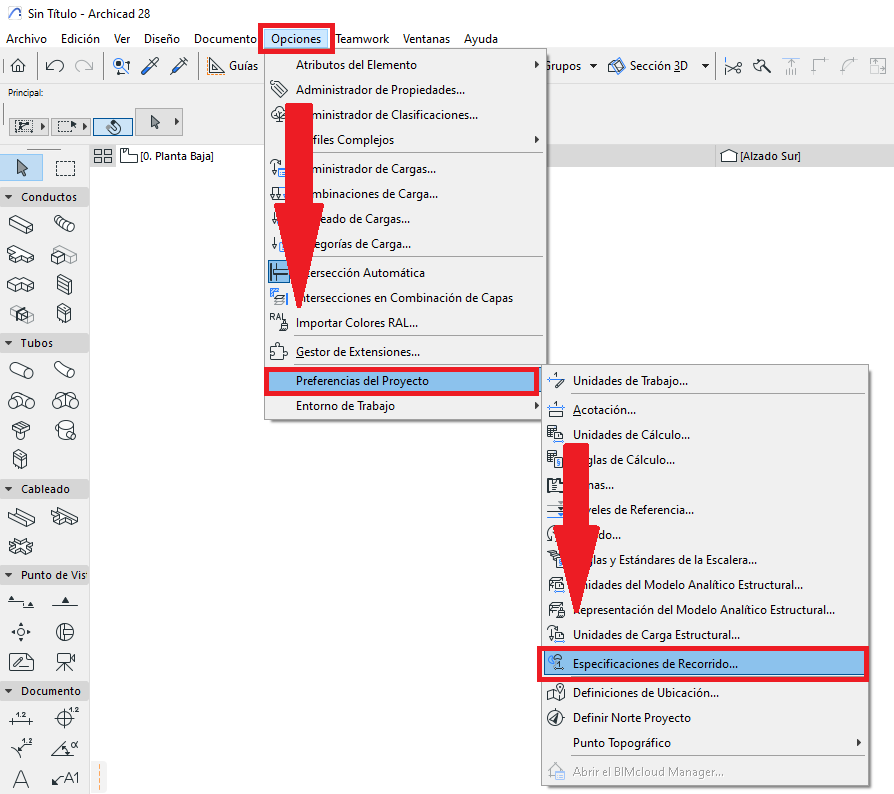
-
Create or Edit Reference Sets
- Select the MEP modelling tool type (Ducts, Pipes, or Cable Trays).
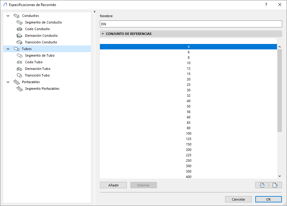
- (Optional) Change the name of the Reference Set (see note 1)
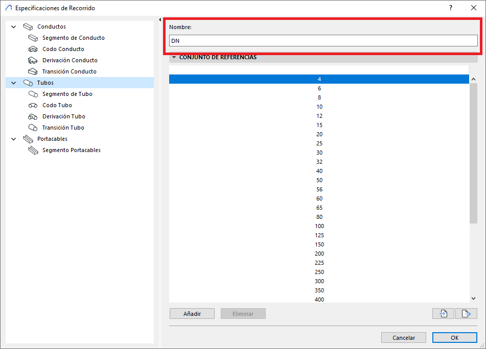
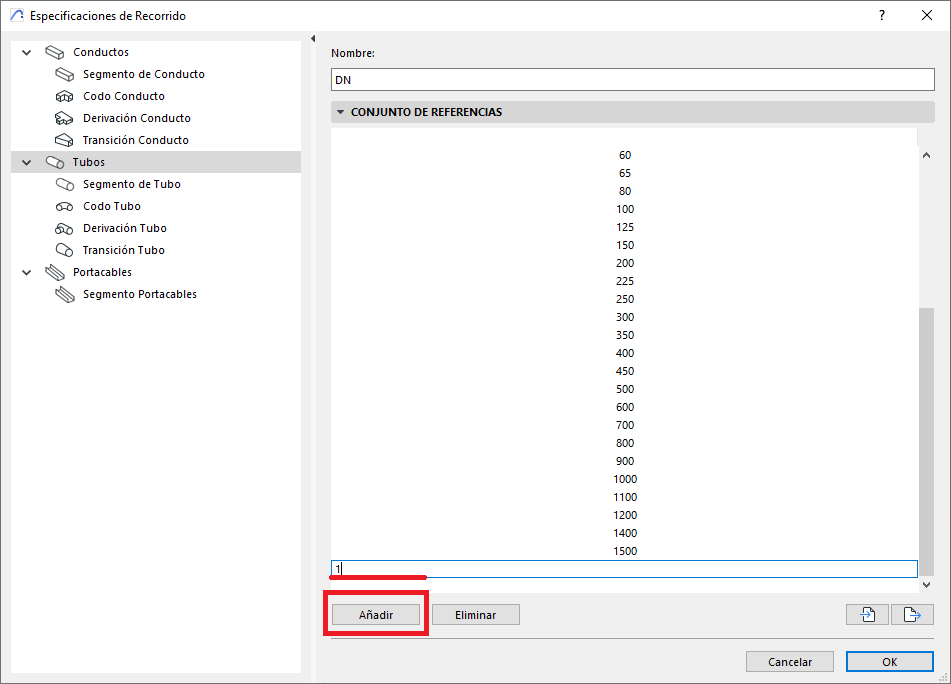
- To add a new dimension to the Reference Set, click Add, and fill in the new field with the new dimension.
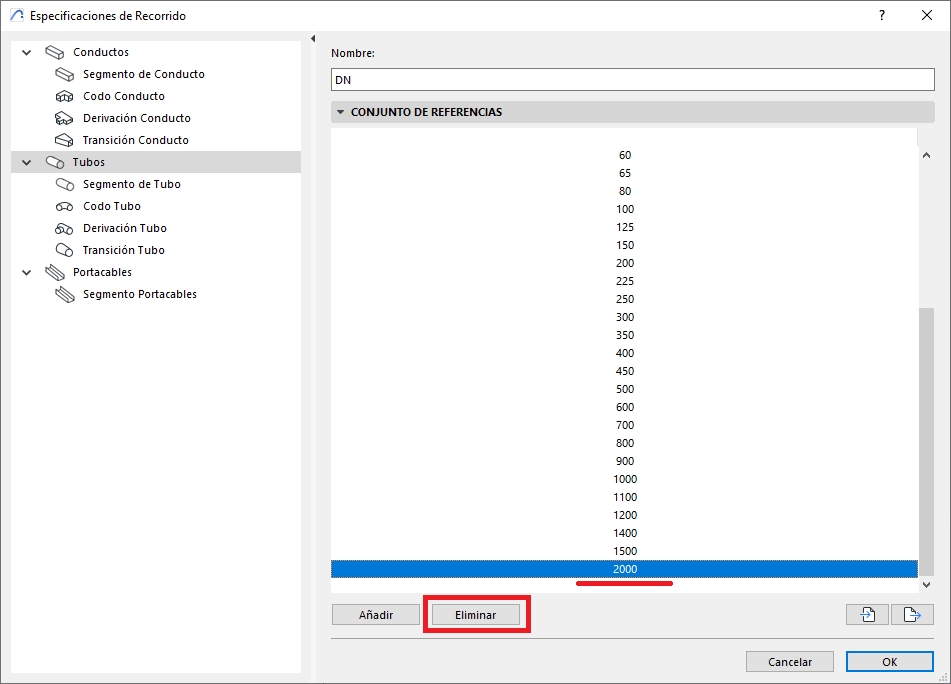
- To remove an existing dimension from the Reference Set, select a reference dimension and click Delete.
- Select the MEP modelling tool type (Ducts, Pipes, or Cable Trays).
-
Define Tables of Dimensions for MEP Components
- In the Route Specifications dialog box, select the branch type (for example Pipe Segment, see image)
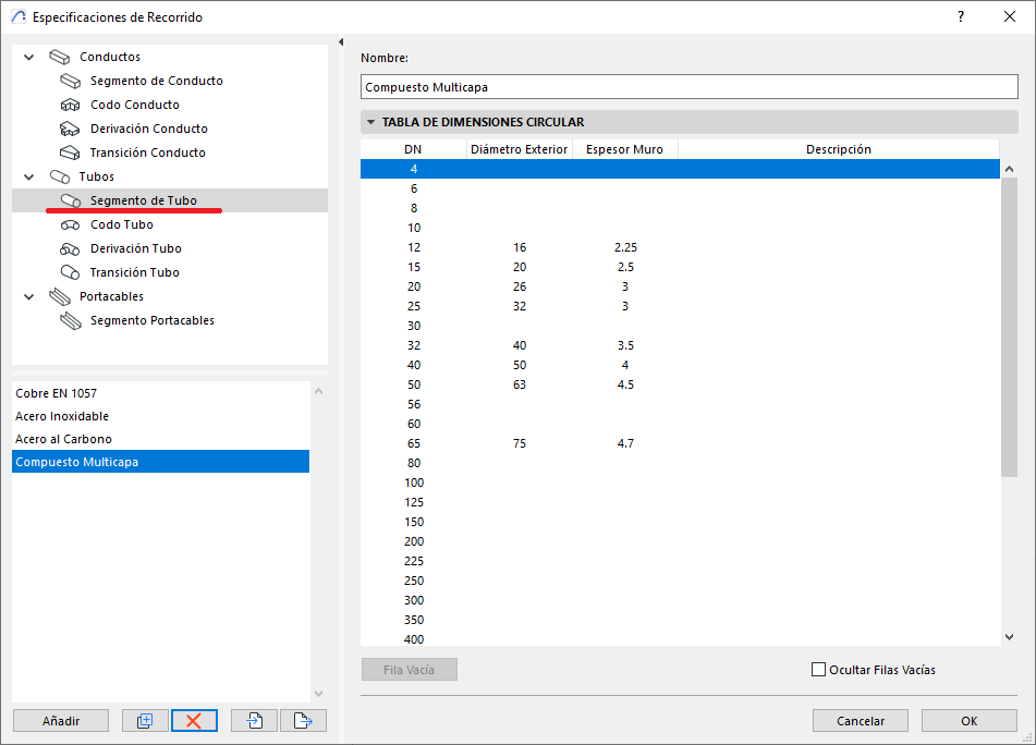
- In the lower panel (see image), the branch type can have different dimensions from the lists of dimensions provided by the Reference Set. These dimensions can be specified by predefined criteria, such as (see image), Pipe Segments can have dimensions specific to the material type.
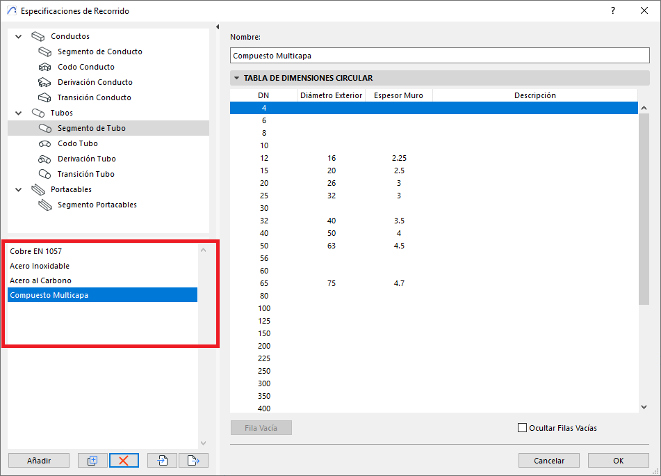
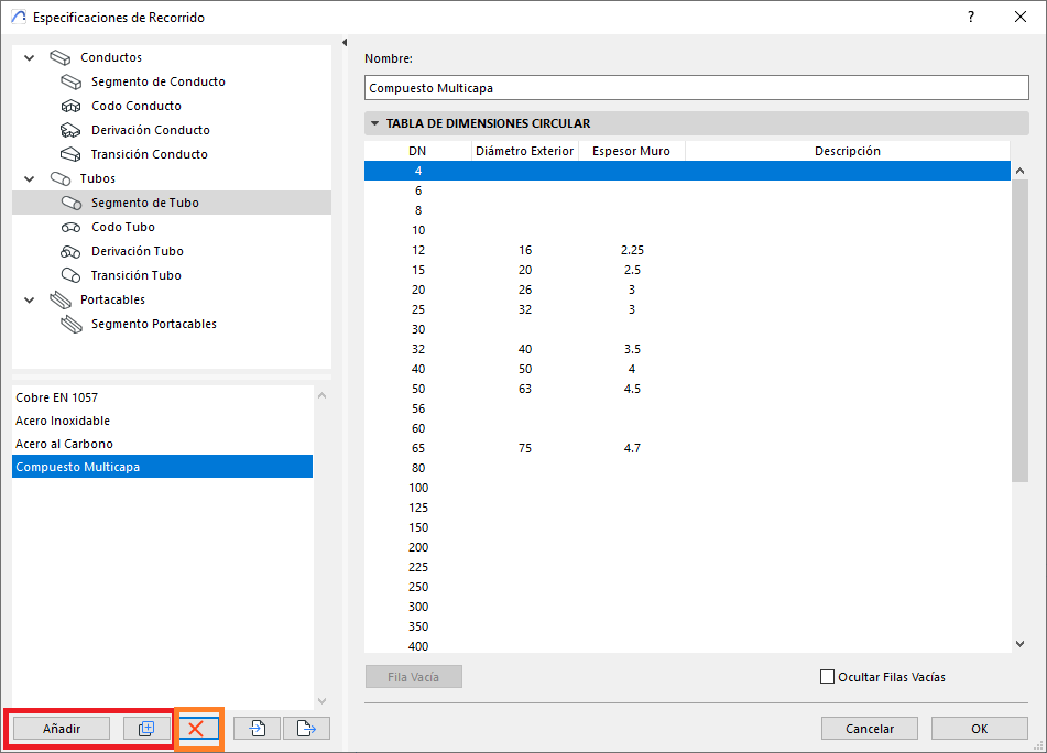
- To add a new table of dimensions, click Add (red). To delete a table of dimensions, select the table and click Delete (yellow).
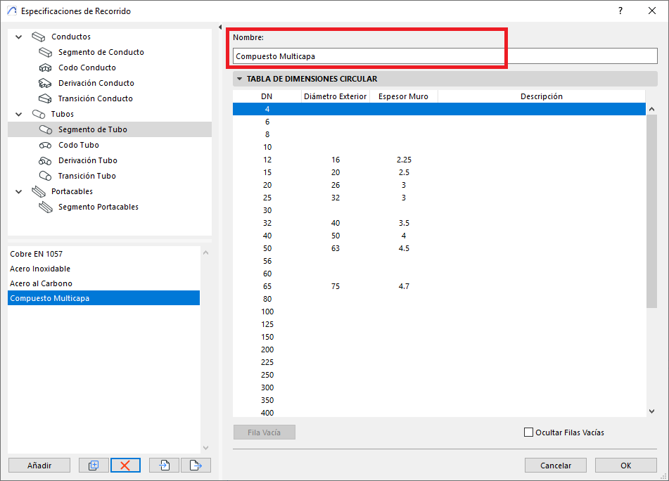
- (Optional) You can change the name of the dimension list under Name (see image)
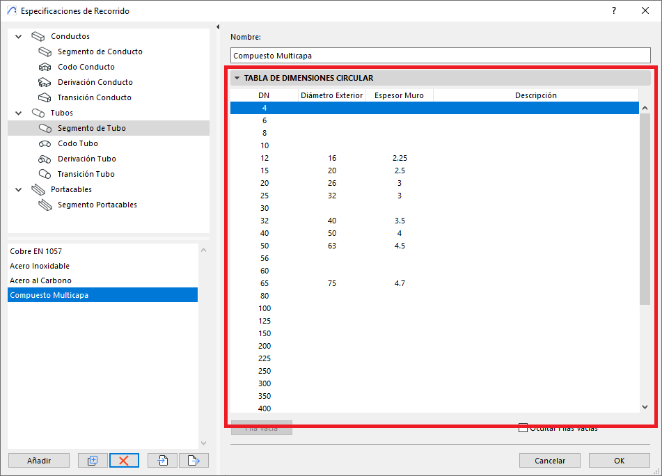
- Specify the dimensions corresponding to the branch type of the MEP element to be modelled, and you can add a Description (see note 2)
- In the Route Specifications dialog box, select the branch type (for example Pipe Segment, see image)
Use a Standardised Naming Convention
We recommend applying clear, consistent conventions when naming:
| Element | Example Name |
|---|---|
| Reference Set | DN_HVAC_ProjectX |
| Table of Dimensions (Segment) | Seg_Hospital_2025 |
| Branch Table | Branch_PEHD_Pipe_90mm |
| Exported XML File | DIM_Tables_MEP_Phase1.xml |
This naming convention improves interoperability and traceability in collaborative projects, and reduces interpretation errors.
Note
- The MEP Modeler can only handle a single Reference Set. The name you give the set will be the one visible in the modelling tool (see example).
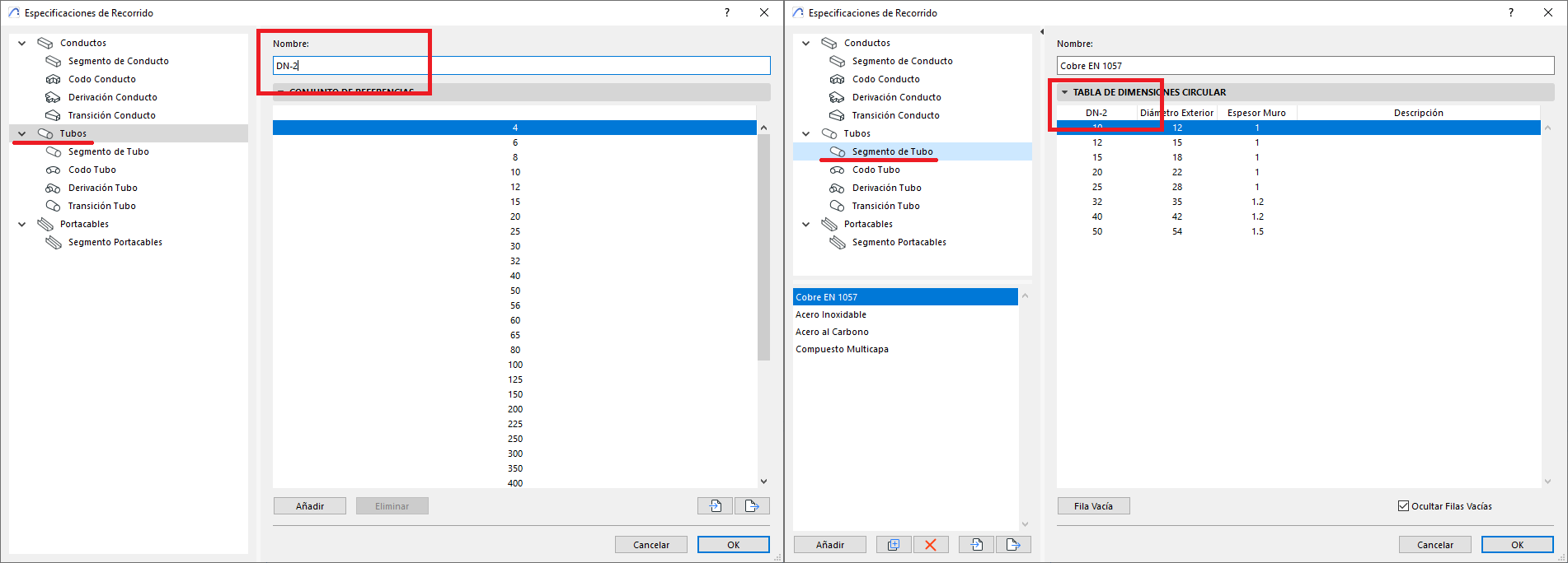
- The measurements entered in the Tables of Dimensions will be the ones available on the MEP elements to be modelled.
BIM Best Practices
We recommend adopting the following best practices:
Centralise in the Project Template:
Define and maintain these configurations within a standard office or company template.
Avoid Redundancy:
Do not create multiple tables with the same dimensions under different names. Only use duplication when functionally necessary.
Technical Validation:
Verify that the dimensions are consistent with manufacturer recommendations or applicable technical standards (for example, ASHRAE, DIN, UNE).
Internal Documentation:
Keep a formal record of all configurations used, by project, version and purpose.
Collaborative Review:
Make sure the tables are reviewed by technical specialists or coordinators before applying them to the model.
Troubleshooting
| Problem | Corrective Action |
|---|---|
| No options appear when selecting the MEP type | Verify that the Reference Set is correctly defined |