
Articles in this section
- How to Uniquely Identify Hotlink Module Zones in Archicad Schedules?
- How to Set the Origin of a 3D Texture in Archicad?
- Why Do Drawings Exported to PDF in Archicad Generate Very Large Files?
- How to Map a Custom Archicad Property to an IFC Property?
- How to Remove an Archicad Educational Licence from a Computer?
- How to Change an Archicad File Started in the International Version to the Spanish Version?
- How to Import a PDF to Use as a Reference in Archicad?
- How to Use Educational and Commercial Versions of Archicad on the Same Computer?
- How to Get the Archicad Connection with Twinmotion?
- How to Create a Structural Frame with the Create Truss Tool in Archicad?
How to Detail Elements of an Imported Model Using 3D Documents in Archicad?
When you need to document a model imported from an IFC file in Archicad, a practical way to do this is to isolate it in 3D, generate several 3D Documents and then place them on a layout.
This workflow lets you obtain a clear representation of the element, create a front view to dimension it correctly and prepare a final presentation with several views of the same component.
Step 1 - Import the file and locate the element
Open the project in Archicad and import the corresponding file. Then, go to the 3D view to locate the element you want to detail.
- Import the IFC file into the model.
- Go to the 3D view.
-
Identify the element you want to document (for example, by marking it in red).
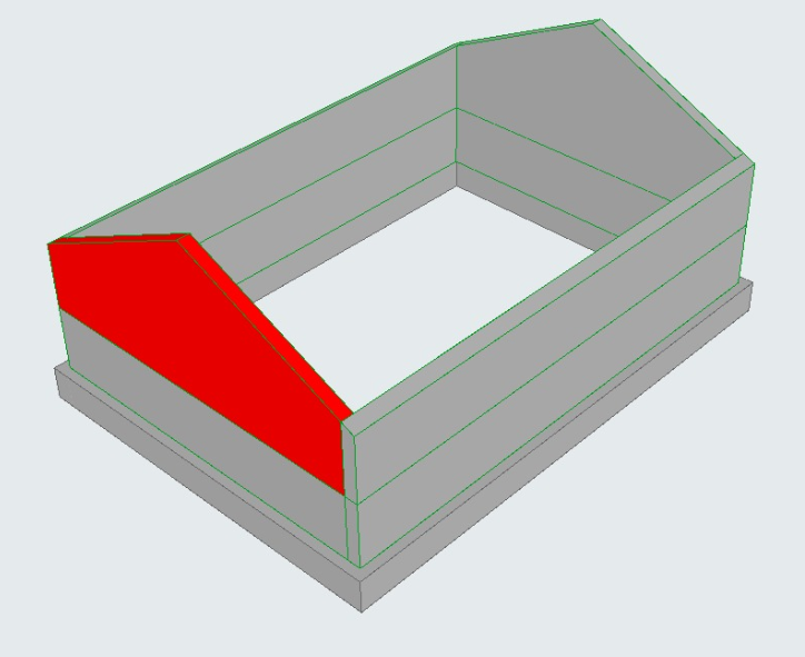
Step 2 - Save a first view as a 3D Document
With the element already located within the model, save the current view as a 3D Document.
- Keep the 3D view of the model visible.
- Save the view as a 3D Document.
Step 3 - Isolate the element in 3D
To work with only the piece you're interested in, select it again and use the Show Selection option.
- Select the element again in the 3D view.
- Right-click on the element.
-
Select Show Selection.
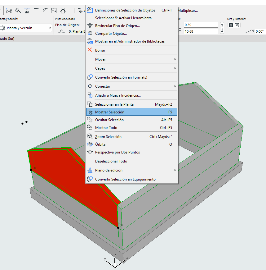
- Save this new isolated view as another 3D Document.
Note: The Show Selection option temporarily hides the rest of the model and leaves only the selected element visible, which makes it easier to produce a much cleaner view.
Step 4 - Set up a front axonometric perspective
Once the element is isolated, you can adjust the projection to get a front view suited for the detail.
-
In the Navigator, activate Axonometric Perspective.
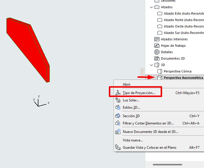
- Right-click on the view and select Projection Type.
- Choose Side View.
-
In the Azimuth field, enter the angle needed to view the element from the front.
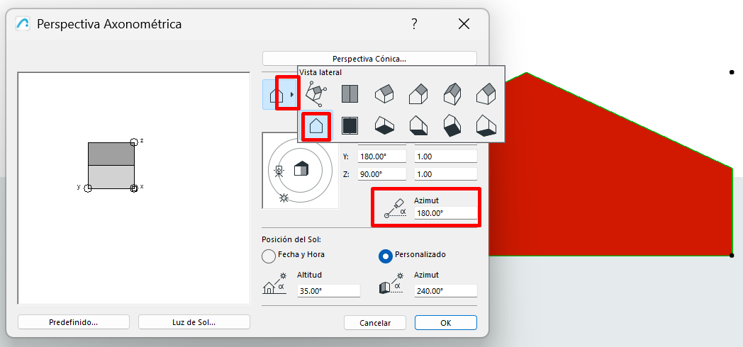
- Save this configuration as a new 3D Document.
Note: The Azimuth value will depend on the element's orientation. If the piece isn't shown exactly front-on, try different angles until you get a clean view that's easy to dimension.
Step 5 - Add dimensions and annotations to the detail
With the front view now defined, you can document the element directly in the 3D Document.
- Open the 3D Document with the front-facing orientation.
- Add the necessary dimensions.
-
Insert text, labels or notes as needed to show the required information.
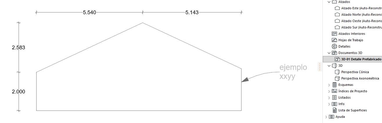
- Save the 3D Documents as Views.
Step 6 - Place the views on the layout
Finally, place the saved views on a layout to compose the final presentation of the detail.
- Go to the Layout.
- Drag the saved views onto the layout.
-
Arrange the composition with the general view, the isolated view and the dimensioned front view.
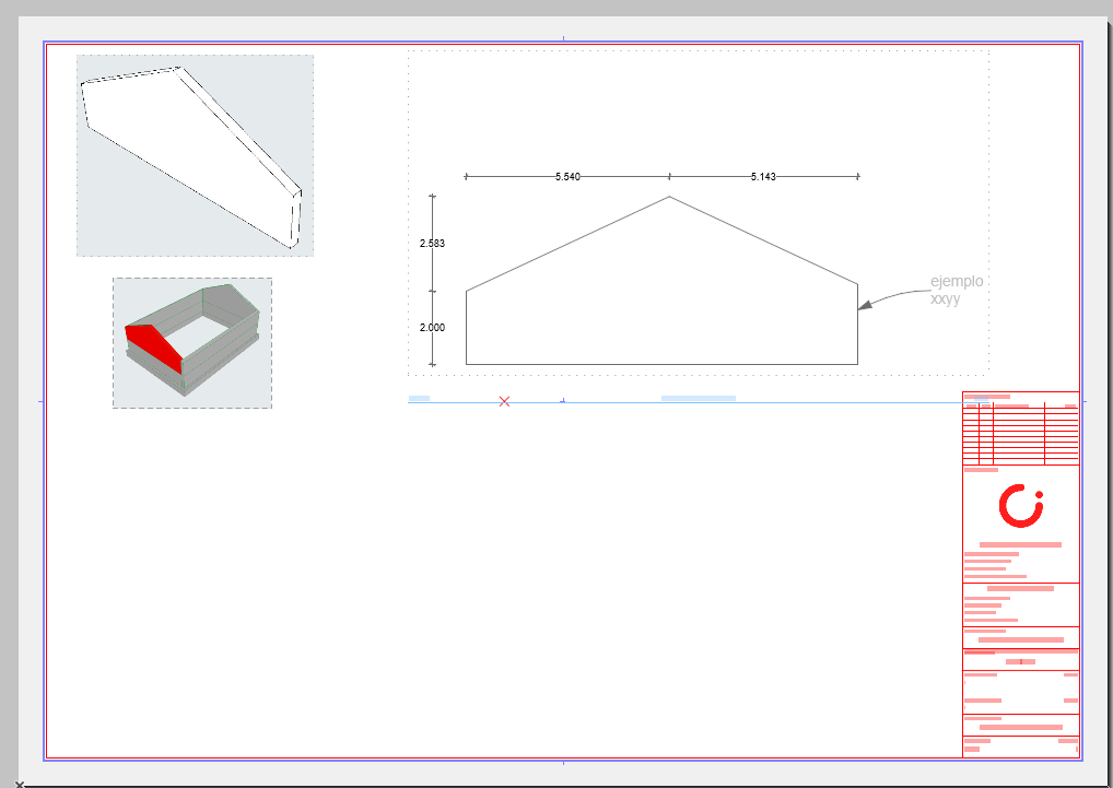
Result
With this workflow you will be able to:
- Isolate an element imported from IFC within the model.
- Generate several useful views using 3D Documents.
- Obtain a front view suited for dimensioning and annotation.
- Prepare a final layout with several views of the element.
Related articles
- How to Uniquely Identify Hotlink Module Zones in Archicad Schedules?
- How to Set the Origin of a 3D Texture in Archicad?
- Why Do Drawings Exported to PDF in Archicad Generate Very Large Files?
- How to Map a Custom Archicad Property to an IFC Property?
- How to Remove an Archicad Educational Licence from a Computer?