
Articles in this section
- How to Uniquely Identify Hotlink Module Zones in Archicad Schedules?
- How to Set the Origin of a 3D Texture in Archicad?
- Why Do Drawings Exported to PDF in Archicad Generate Very Large Files?
- How to Map a Custom Archicad Property to an IFC Property?
- How to Remove an Archicad Educational Licence from a Computer?
- How to Change an Archicad File Started in the International Version to the Spanish Version?
- How to Import a PDF to Use as a Reference in Archicad?
- How to Use Educational and Commercial Versions of Archicad on the Same Computer?
- How to Get the Archicad Connection with Twinmotion?
- How to Create a Structural Frame with the Create Truss Tool in Archicad?
How to Document the Coordinates of Project Elements?
Sometimes it's necessary to document the coordinates of elements (or points of interest) for various reasons. By following the steps below, you can extract that information effectively.
1. Prepare the Views
Only activate or keep visible the elements whose coordinates you want to extract. Make sure the Partial Structure Display, the Available Pen Sets, the Model View Options, the Graphic Override Combinations, the Renovation Filter Options and the Design Option Manager are configured correctly.
Then, turn the layers of the elements of interest off and on and save the configuration as a Layer Combination. Don't forget to give that Layer Combination a descriptive name indicating its final purpose.
2. Find the Coordinates Object
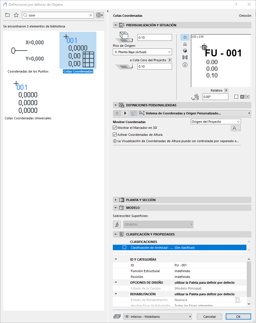
Open the Object Tool and type "Coordinates" in the search box. You will get a result similar to the image below.
3. Select the Coordinates Object
Depending on the project's requirements, use:
- Coordinate Dimensions: to extract the coordinates (X, Y, Z) of the points of interest relative to the project.
- Universal Coordinate Dimensions: to extract the universal coordinates (North, South, East or West, and Altitude) of the points of interest in the project.
Note: Don't forget to configure the General Settings of the Coordinates Object or the Universal Coordinate Dimensions.
4. Place the Object at the Points of Interest
Place the selected coordinates object at the relevant points throughout the project.
Note: It is good practice that:
- The Coordinate Dimensions or Universal Coordinate Dimensions object used for this specific case is placed on its own layer.
- The ID of the Coordinates object is configured so that it references the element of interest whose coordinates are required.
5. Create a Schedule for the Coordinates
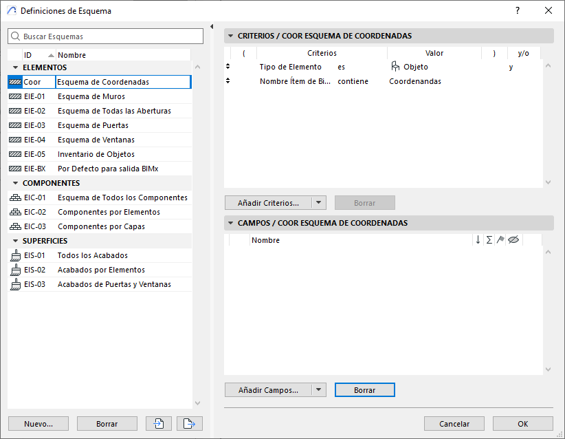
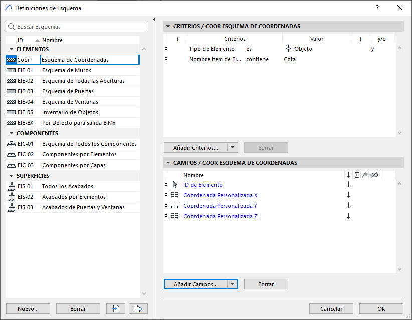
In Scheme Settings, create a new schedule with the following Criteria:
- Element Type: Object
- Library Part Name: contains "Coordinates"
Note: Other Archicad object filtering criteria also apply.
6. Extract the Coordinates from the Coordinates Object
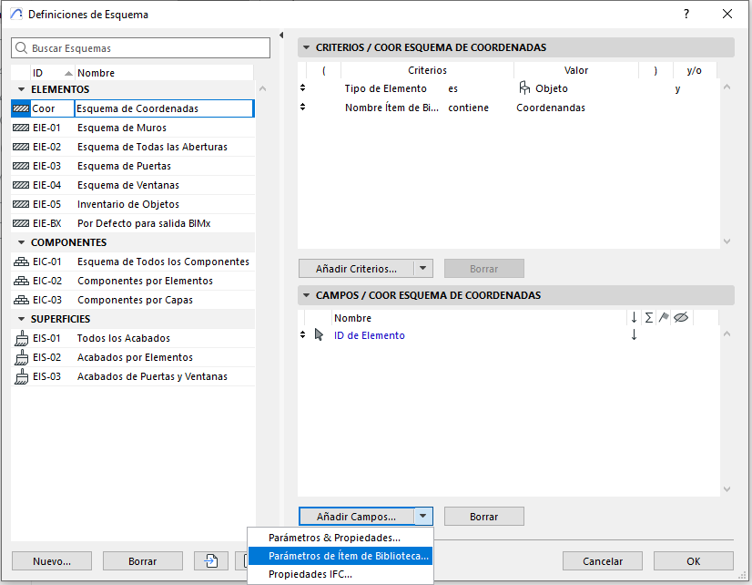
In Scheme Settings, add the Element ID field.
Then, to extract the coordinates, click the black arrow next to "Add Fields...", and select "Library Part Parameters...".
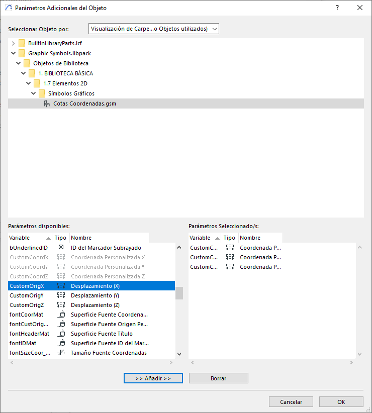
In the Additional Object Parameters dialog box, select the "Folder View (Used Objects Only)" option, select the coordinates object used in the project, and under Available Parameters select CustomCoordX, CustomCoordY and CustomCoordZ. Click the ">> Add >>" button and OK.
7. Review the Coordinates Schedule
Check that the coordinates schedule has the necessary data, and it should look similar to the image below.
By following these steps and incorporating these tips, you can successfully extract the coordinates of elements in your Archicad project. If you have any questions or need further help, don't hesitate to ask us!
Related articles
- How to Uniquely Identify Hotlink Module Zones in Archicad Schedules?
- How to Set the Origin of a 3D Texture in Archicad?
- Why Do Drawings Exported to PDF in Archicad Generate Very Large Files?
- How to Map a Custom Archicad Property to an IFC Property?
- How to Remove an Archicad Educational Licence from a Computer?