
Articles in this section
- How to Uniquely Identify Hotlink Module Zones in Archicad Schedules?
- How to Set the Origin of a 3D Texture in Archicad?
- Why Do Drawings Exported to PDF in Archicad Generate Very Large Files?
- How to Map a Custom Archicad Property to an IFC Property?
- How to Remove an Archicad Educational Licence from a Computer?
- How to Change an Archicad File Started in the International Version to the Spanish Version?
- How to Import a PDF to Use as a Reference in Archicad?
- How to Use Educational and Commercial Versions of Archicad on the Same Computer?
- How to Get the Archicad Connection with Twinmotion?
- How to Create a Structural Frame with the Create Truss Tool in Archicad?
How to Verify Project Requirement Compliance in Archicad? Space Area Control – Graphic Option
Reading time: 8 min.
A technical team developing architectural projects in Archicad works on projects with precise requirements for the minimum area of different types of spaces: offices, technical rooms, corridors, among others. During development, the reference values can change due to client decisions or updated regulations.
Instead of checking compliance manually, a method is implemented that takes advantage of the automation possibilities in Archicad to check whether the modelled spaces meet the previously established area requirements graphically, providing traceability, flexibility in the face of changes and time savings during reviews.
Target Audience
Intermediate Archicad users, BIM technicians, implementation consultants, and support staff who need to check quantitative model data.
Prerequisites
- Archicad 25 or later
- Project with Zones correctly modelled and classified
- Basic knowledge of custom Properties, Interactive Schedules, and Graphic Overrides in Archicad.
- A custom Property that automates checking compliance with the project's requirements.
- Reading of the following articles:
Solution Steps
-
Review the 3D View
Open a 3D View of the project, and make sure it has a 3D Style enabled that shows the Zones in colour on their surfaces. This visualisation is essential for later applying surface-based Overrides (see example image).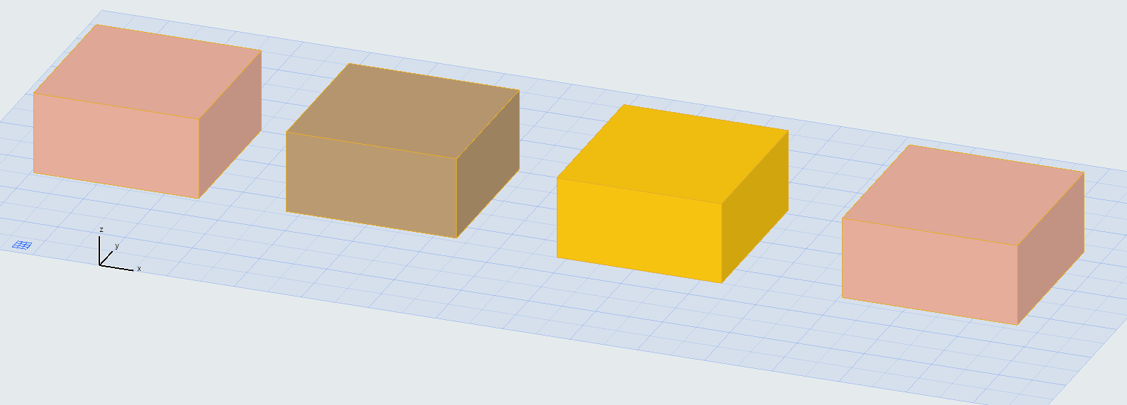
-
Check That You Have a Custom Property Suitable for the Graphic Override
For this example, the custom Property will beSup_Req_Tipo_Verificación, which is the one configured in the article: How to Verify Project Requirement Compliance in Archicad? Space Area Control – Semi-Automated Option – My SIMBIM Centre
If you do not have this type of property, use the article mentioned above as a guide.
-
Create a Graphic Override Combination
- Go to: Document > Graphic Overrides > Graphic Override Combinations.
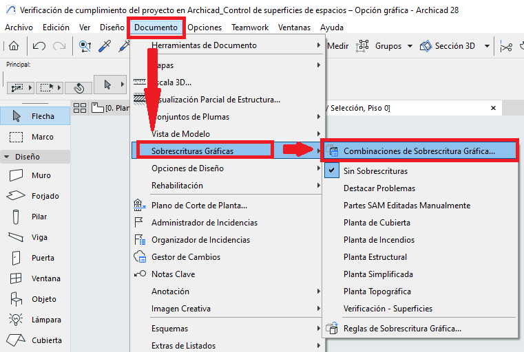
- In the Graphic Override Combinations dialog box, click New to create a Graphic Override Combination, with a descriptive name, for example: Verification - Areas.
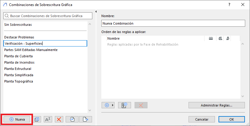
- Go to: Document > Graphic Overrides > Graphic Override Combinations.
-
Define Override Rules
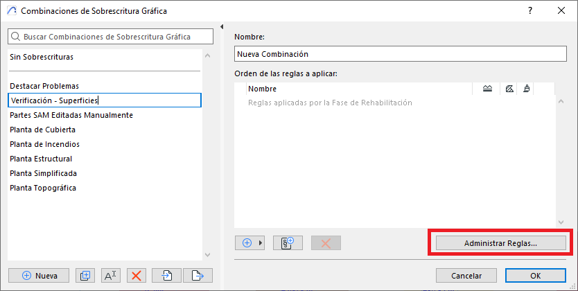
- In the Graphic Override Combinations dialog box, click Edit Rules... to create the new Graphic Override Rules.
-
Create a new rule group:
In the Graphic Override Rules dialog box, click to create a new rule group named Area Verification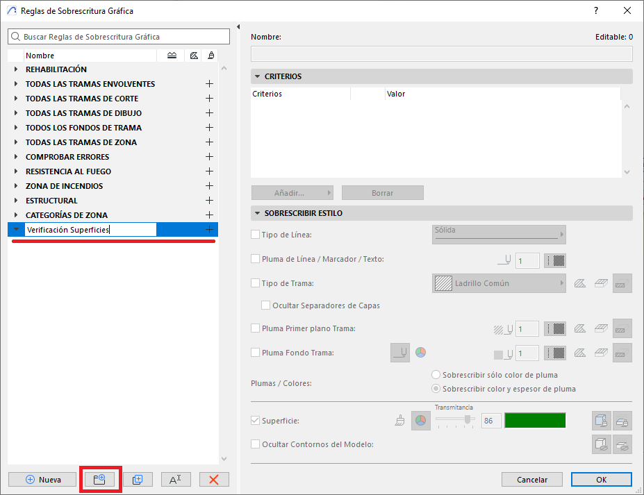
-
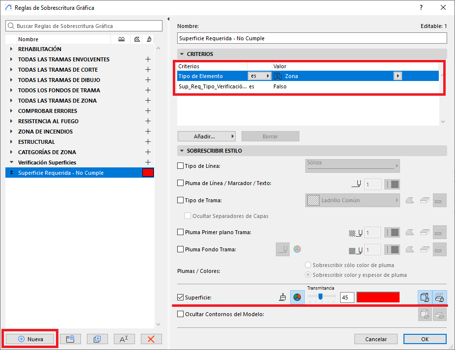
"Required Area – Not Met" Rule:
Click New, with the following specifications:- Element Type: Zone
- Property: Sup_Req_Tipo_Verificación = False
-
Override Style: Surface, with a reddish colour and transparency, applied to the element's surfaces and its sections.
-
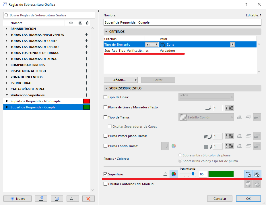
(Optional) "Required Area – Met" Rule:
Repeat the previous step for the surfaces that do meet the requirements, changing:- Property: Sup_Req_Tipo_Verificación = True
-
Override Style: Surface, with a greenish colour and transparency, applied to the element's surfaces and its sections.
-
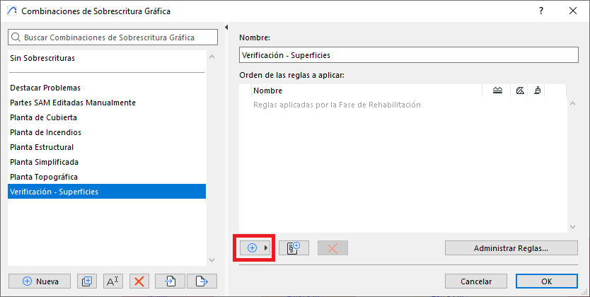
Assign the Rules to the Graphic Override Combination:
- Click OK.
- In the Graphic Override Combinations dialog box, click Add Existing Rule(s) and select the rules you have just created, then click OK.
- In the Graphic Override Combinations dialog box, click Edit Rules... to create the new Graphic Override Rules.
- Activate in the 3D View
Open the 3D View and apply the Graphic Override Combination you have created, which should generate a view like the following image.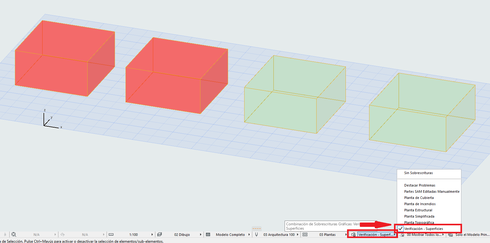
Note for the Reader
The Graphic Override Combinations and Override Rules presented in this article have been intentionally simplified for demonstration purposes. In a real project environment, these rules may require additional adjustments to address spatial typologies, multiple functional categories or specific validations. This simplification makes it easier to understand the methodology without compromising the technical concept.
Common Troubleshooting
| Problem | Solution |
|---|---|
| The zones do not appear in colour | Check that the 3D Style shows Zone surfaces |
| The rules are not applied | Check that the Sup_Req_Tipo_Verificación property is correctly assigned |
| Incorrect colours | Check the order and combination of rules in the override |
Sample File:
You can download a sample project file where an Interactive Schedule has been correctly set up with a custom property that counts elements by unit:
Related articles
- How to Uniquely Identify Hotlink Module Zones in Archicad Schedules?
- How to Set the Origin of a 3D Texture in Archicad?
- Why Do Drawings Exported to PDF in Archicad Generate Very Large Files?
- How to Map a Custom Archicad Property to an IFC Property?
- How to Remove an Archicad Educational Licence from a Computer?